


 Email:
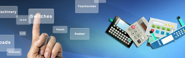
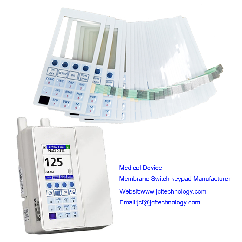
Membrane switch is a printed electronic circuit that uses pressure to open and close a circuit. The membrane switch circuitry is most often screen printed using conductive inks, which are typically made of silver, carbon, and or graphite.
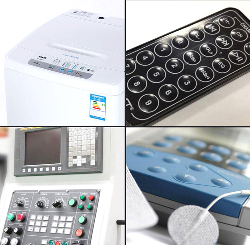
Membrane switches are part of a range of devices considered to be user interfaces (also called operator interfaces, or man machine interfaces) along with display-based touch screens, and mechanical switches such as push-button, toggle, rocker,and slide switches. The ultimate purpose of a membrane switch is to serve as the interface between man and machine,enabling an operator to communicate with a piece of equipment, instrument, or machinery.
Completely sealed surface – easily cleaned and sterilized
Low Profile – no crevices that can trap contaminants
A cost-effective alternative – less costly than rubber keypad assemblies and capacitive touch keypads
Thin profile – saves valuable space in your product design
Easy to interface with existing controllers – no special electronics required, as with touch screens
Versatile graphic interface – overlays can be screen or digitally printed with stunning, photo-quality graphic effects
Protection by design – Easier to protect from UV radiation than rubber keypads
Water-resistant designs – meets NEMA 4 and IP 67 specifications
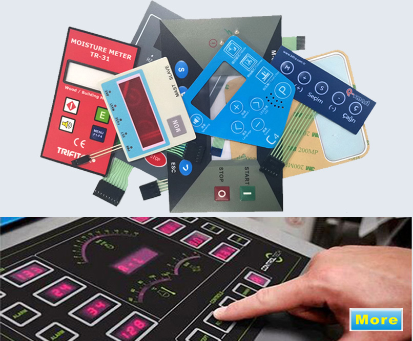
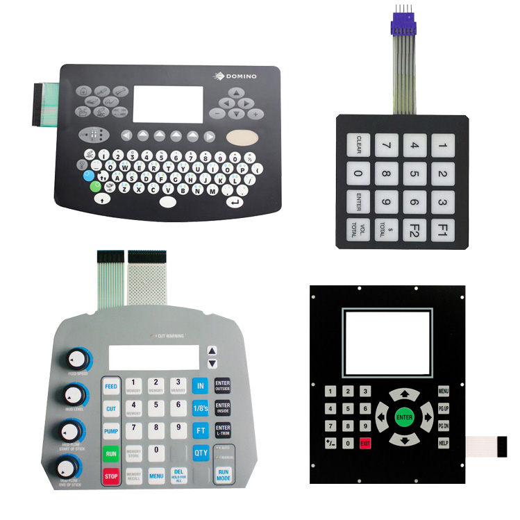
Membrane switches are essentially a sandwich of thin layers that are bonded together using pressure sensitive adhesives. Depending on the application requirements, a membrane switch will consist of as few as 4, and as many as 9 layers. In contrast to mechanical switches, membrane switches offer the advantage of lower cost, they consume less design space with their low profile, are easy to clean, and they offer a sleeker, ergonomic, and aesthetically pleasing appearance.
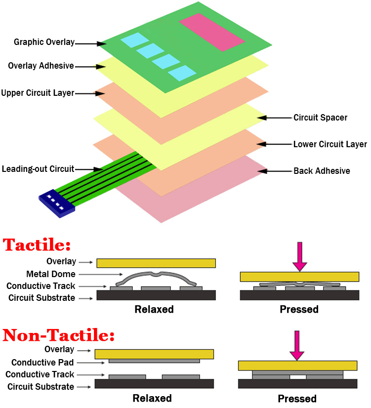
The visible top layer of a membrane switch is the graphic overlay, with printed circuitry underneath the overlay. The circuitry can also incorporate different layers such as polyester (silver flex), polyimide (copper flex), and rigid PCB layers. Activation of a switch occurs when a printed shorting pad or metal dome makes contact with the bottom circuit layer thus, closing the circuit.
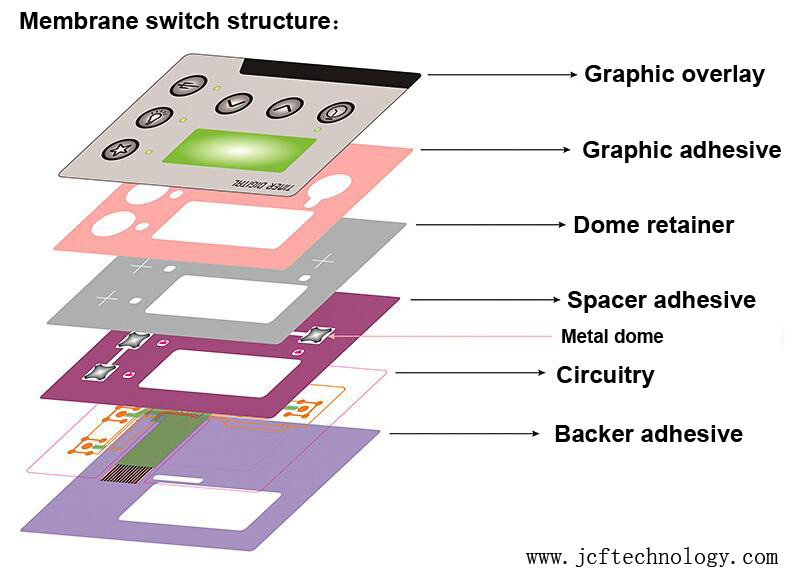
1. Graphic Overlay – Polyester is usually the material of choice due to its superior chemical resistance and flex life compared to polycarbonate. Pannam can either digitally print, screen-print, or employ a combination of both methods to ensure you get the right colors, textures and finishes your design requires. custom membrane switches manufactured by Pannam.
2. Overlay Adhesive – This adhesive layer bonds the graphic overlay to the top circuit layer, and is typically an acrylic adhesive.
3. Top Circuit Layer – This is a 0.005″ – 0.007″ heat stabilized polyester printed with silver-filled electrically conductive inks and also dielectric inks.
4. Circuit Spacer – This layer separates the top circuit from the bottom circuit so the switch remains normally open until the keypad is pressed. The circuit spacer is a polyester spacer with adhesive on both sides.
5. Lower Circuit Layer – This is a 0.005″ – 0.007″ heat stabilized polyester printed with silver-filled electrically conductive inks and also dielectric inks. This layer terminates as a flexible tail that serves as the interconnect to controller PCBs or other electronics.
6. Rear Adhesive Layer – This adhesive layer bonds the entire membrane switch package to the product enclosure, housing,or to a rigid support panel. Pannam can specify the appropriate adhesive type and thickness to bond your membrane keypad to your equipment.
7. Rigid Support Layer – This optional layer can add structural integrity to the membrane switch assembly.
1 Electrical Performance
(1) Operating Voltage: ≤50VD
(2) Operating Current: ≤100mA
(3) Contact Resistance: 0.5~10Ω
(4) Insulation Resistance: ≥100MΩ(100VDC)
(5) Base Material Withstand: 2kDVC
(6) Contact bounce: ≤6ms
(7) Loop Resistance: 50Ω,150Ω,350Ω or as per clients’ requirement
2 Mechanical Properties
(1) Life expectancy: >1 million times
(2) Switch stroke: 0.1-0.4mm(Flat type)0.4-1.0mm(Tactile type)
(3) Actuation force: 15~750g
(4) Flex Tail Pitch(Standard): 2.54 /2.50 /1.27/ 1.25mm
3 Environment Specification
(1) Operation Temperature: -20°C~+70°C
(2) Storage temperature: -40°C~+85°C
(3) Humidity: 40 C, 90%-95%, 240 hours
4 Printing Indicator
(1) Size Deviation: ±0.15mm
(2) Side Boundary: ≤0.1mm
|
Electrical Properties: |
|
|
Rated Voltage |
≤50V DC |
|
Rated Current |
≤ 100mA |
|
Operating Power |
≤1W |
|
Insulation Resistance |
≥100MΩ (250V DC) |
|
Loop Resistance |
10Ω~2kΩ (based on the design) |
|
Contact Resistance |
0.5 ~ 5Ω |
|
Wire Lead Resistance |
<1Ω/cm |
|
Base Material Voltage Withstand |
1500V DC |
|
Mechanical Properties: |
|
|
Life Expectancy |
Flat type ≥ 5 million times, Tactile type ≥ 1 million times |
|
Operation Force |
Flat Type 57-284g ,Tactile Type 170-397g |
|
Dome Rebound Time |
≤6ms |
|
Tail Bending Performance |
≤180° |
|
Switch Stroke |
Flat 0.1~0.5mm,Tactile 0.6~1.5mm |
|
Vibration |
20G's max. |
|
Thickness |
0.7~1.5 mm |
|
Environmental Properties: |
|
|
Operation Temperature |
-40°C to +80°C (-40°to 176°F) |
|
Storage Temperature |
-40°C to +85°C (-40°to 185°F) |
|
Atmospheric Pressure |
86 ~ 106 kPa |
|
Humidity |
+40°C, 90%~95%RH for 240 Hours |
Contact us:
Email:jcf@jcftechnology.com
Phone:+8613715205860(Wechat)

